Tmraju1 i will design or draw electrical drawing and floor plan for 5
Table of Contents
Table of Contents
Are you struggling with how to draw electrical diagrams in autocad? It can be a daunting task, especially if you’re new to the software. But not to worry, with the right guidance, anyone can master this skill and create professional-grade electrical diagrams with ease.
Creating electrical diagrams in autocad can be time-consuming and frustrating, especially if you’re not familiar with the software’s features and capabilities. It can also be challenging to ensure accuracy and precision in your diagrams, which is critical when dealing with electrical systems. But with the right techniques and tools, you can streamline the process and create precise diagrams that meet all industry standards and regulations.
To draw electrical diagrams in autocad, you must first understand the basics of the software, including its tools and functions. You must also have a good understanding of electrical symbols and terminology, as well as the specific requirements for the type of diagram you’re creating.
In summary, to draw electrical diagrams in autocad, you need to:
Understanding Autocad for Electrical Diagrams
When I first started drawing electrical diagrams in autocad, I found it extremely challenging. The software was overwhelming, and I wasn’t sure where to start. But with time and practice, I learned some valuable techniques that helped me streamline the process and create precise diagrams in less time.
First and foremost, it’s essential to understand autocad’s basic tools and functions. These include the line tool, dimension tool, text tool, and block tool, among others. You must also understand how to use layers to organize your drawings and make the editing process easier.
Another essential aspect of drawing electrical diagrams in autocad is familiarity with electrical symbols and terminology. There are specific symbols used in electrical diagrams that represent various components, such as switches, motors, transformers, and more. Understanding these symbols and their meanings is critical to creating accurate diagrams.
The Importance of Accuracy in Electrical Diagrams
When it comes to electrical diagrams, accuracy is of utmost importance. These diagrams are vital to the safe and efficient operation of electrical systems, and any errors or omissions can lead to serious consequences, such as equipment failure or electrical fires.
To ensure accuracy in your diagrams, you must be familiar with industry standards and regulations, such as the National Electric Code (NEC), which outlines guidelines for the installation and maintenance of electrical systems. You must also be diligent in your work, double-checking your diagrams for errors and omissions before finalizing them.
A Step-by-Step Guide to Drawing Electrical Diagrams in Autocad
Here’s a step-by-step guide to help you create accurate and precise electrical diagrams in autocad:
Step 1: Start a new drawing and set up the environment
Open autocad and start a new drawing. Set your units to match the project requirements, and create a new layer for each component of the diagram, such as switches, motors, and lights.
Step 2: Add symbols to the drawing
Use the block tool to add symbols to the drawing. Ensure that each symbol is on the appropriate layer, and use the copy and paste commands to save time when adding multiple instances of the same symbol.
Step 3: Add wiring and connections
Use the line tool to draw wiring and connections between the symbols. Use the appropriate layer for each wire, and ensure that each wire is connected to the correct components.
Step 4: Add dimensions and annotations
Use the dimension tool to add dimensions to the drawing, including the overall size of the diagram and the size and location of individual components. Add annotations to provide additional information about the components or the diagram as a whole.
Tips and Tricks for Drawing Electrical Diagrams in Autocad
Here are a few tips and tricks that can help you create professional-grade electrical diagrams in autocad:
- Use layers to organize your drawing and make the editing process easier.
- Use the copy and paste commands to save time when adding multiple instances of the same symbol.
- Use the snap and grid tools to ensure that wiring and connections are aligned properly.
- Use the stretch command to adjust the size and position of components without having to delete and redraw them.
- Use the plot command to print your diagram to scale and ensure that every aspect is accurate.
Question and Answer
Q: Can I use autocad LT to draw electrical diagrams?
A: Yes, you can use autocad LT to draw electrical diagrams. However, some features and tools may not be available in LT compared to the full version of autocad.
Q: Are there any shortcuts I can use to speed up my drawing process in autocad?
A: Yes, there are several shortcuts you can use to speed up your drawing process in autocad. For example, you can use the copy and paste commands to save time when adding multiple instances of the same symbol. You can also use the stretch command to adjust the size and position of components without having to delete and redraw them.
Q: How can I ensure that my electrical diagram meets industry standards and regulations?
A: To ensure that your electrical diagram meets industry standards and regulations, you must be familiar with the specific requirements for the type of diagram you’re creating. You must also be familiar with industry standards and regulations, such as the National Electric Code (NEC), which outlines guidelines for the installation and maintenance of electrical systems.
Q: What is the best way to print my electrical diagram to scale?
A: To print your electrical diagram to scale, you can use the plot command in autocad. This command allows you to specify the scale, paper size, and other printing options to ensure that your diagram is printed accurately and to scale.
Conclusion
Drawing electrical diagrams in autocad can be a challenging task, but with the right techniques and tools, you can create accurate and precise diagrams that meet all industry standards and regulations. Remember to use layers to organize your drawings, be familiar with electrical symbols and terminology, and ensure accuracy and precision in your work. By following these tips and tricks, you can streamline the process and create professional-grade electrical diagrams in no time.
Gallery
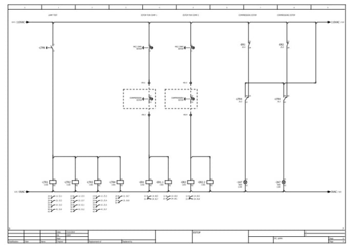
Draw Electrical Schematic Diagrams Using Eplan By Yas_89 | Fiverr

Photo Credit by: bing.com / electrical eplan diagrams draw schematic using fiverr screen
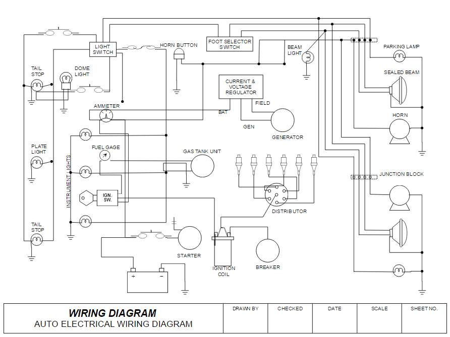
How To Draw Electrical Diagrams And Wiring Diagrams

Photo Credit by: bing.com / electrical draw diagrams diagram wiring circuit example circuits template line
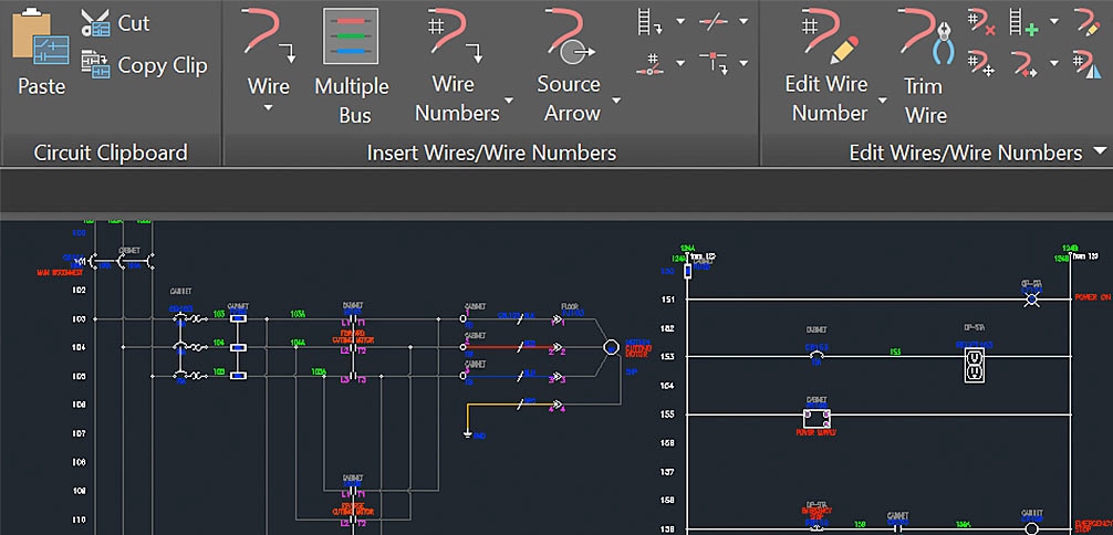
Electrical Drawing | Software & Resources | Autodesk

Photo Credit by: bing.com / electrical drawing autodesk software drawings engineering use
Tmraju1: I Will Design Or Draw Electrical Drawing And Floor Plan For $5

Photo Credit by: bing.com / wiring electrical schaltplan elektrotechnik edrawmax electrics layout motorola elektrische elektrischer bookingritzcarlton edrawsoft rowville regelkreis
Cad Drawing Wiring Diagram

Photo Credit by: bing.com / autocad schematic contactor webinars


