Drawing ladder logic computer icons diagram
Table of Contents
Table of Contents
Have you ever felt overwhelmed by the process of drawing a ladder diagram? Well, fear not, because in this article, we will provide you with step-by-step instructions on how to draw a ladder diagram. Whether you’re an electrician or an engineer, understanding how to draw a ladder diagram is essential to your profession.
When it comes to drawing ladder diagrams, many people struggle with knowing where to start and how to organize their diagram. Without proper guidance, it can be time-consuming and frustrating to complete. Additionally, if the diagram is not properly laid out, it can lead to confusion for anyone looking at it.
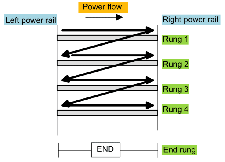
Firstly, it’s important to understand that a ladder diagram is a graphical representation of a control circuit. It uses symbols to show the components of the circuit and how they are connected. The diagram resembles a ladder, with two vertical bars representing the power rails, and horizontal bars representing the components connected to them.
To draw a ladder diagram, you should start by identifying the input and output devices. These may include push buttons, switches, relays, and motors. Once you have identified these components, you can begin to draw the diagram using standardized symbols. The symbols are easy to identify and can be found in any ladder diagram library.
My experience with drawing a ladder diagram
As an electrical engineer, I have had plenty of experience drawing ladder diagrams. My first time drawing one was a bit intimidating, but with some guidance from my mentor, I was able to create a functional diagram. One tip that has helped me in the process is to always start by creating a rough sketch of the circuit before transferring it to the final diagram. This way, you can ensure that all components are properly connected.
Steps to draw a ladder diagram
Step 1: Identify the input and output devices. This includes switches, sensors, motors, and lights.
Step 2: Identify the power supply and the required voltage needed for the circuit.
Step 3: Determine the logic of the circuit. This will dictate the sequence in which the components are activated.
Step 4: Draw the components and connect them using standard symbols.
Ladder diagram symbols
There are several standardized symbols used in ladder diagrams. These symbols include:
- Coil
- Contact
- NO Contact
- NC Contact
- Motor
- Push Button
- Timer
Coil symbol
The coil symbol is used to represent a relay or an electromagnet. It is represented by a circle with a single line passing through it. The line represents the magnetic field that is generated when a current passes through the coil.
Contact symbol
The contact symbol is used to represent a switch or a sensor. It is represented by a straight line that is either open or closed. An open contact means that the switch is not activated, while a closed contact means that the switch is activated.
Tips for drawing a ladder diagram
When drawing a ladder diagram, it’s important to keep the following tips in mind:
- Use standardized symbols for each component to ensure clear communication.
- Draw the diagram in a logical sequence to ensure easy interpretation.
- Double-check all wiring connections to ensure accuracy.
- Label each component to avoid confusion.
Question and Answer Section
1. What is a ladder diagram used for?
A ladder diagram is used to represent a control circuit in a graphical form.
2. What are the components of a ladder diagram?
The components of a ladder diagram include input devices such as switches and sensors, output devices such as motors and lights, power supply, and logic components.
3. Why is it important to use standardized symbols in a ladder diagram?
Using standardized symbols ensures clear communication between individuals who may be located in different parts of the world.
4. How can you ensure the accuracy of a ladder diagram?
You can ensure accuracy by double-checking all wiring connections before finalizing the diagram.
Conclusion of how to draw a ladder diagram
Understanding how to draw a ladder diagram is an important skill for anyone in the electrical or engineering fields. By following the steps outlined in this article and keeping in mind the tips provided, you’ll be well on your way to creating clear and accurate diagrams. Remember to use standardized symbols, label each component, and double-check all connections to ensure accuracy.
Gallery
Drawing Ladder Logic Computer Icons Diagram - Ladder Drawing
![]()
Photo Credit by: bing.com / ladder drawing diagram logic icons computer cartoon netclipart rope
What Is Ladder Diagram And How To Draw A Ladder Diagram?

Photo Credit by: bing.com /
Ladder Diagrams - YouTube

Photo Credit by: bing.com /
The PLC Ladder Diagram. | Download Scientific Diagram

Photo Credit by: bing.com / ladder
Ladder Diagram Basics #1 | Diagram, Ladder Logic, Electrical Diagram

Photo Credit by: bing.com / ladder toaster plc draw


