Solved you have a 180 resistor and a 0 370 h inductor
Table of Contents
Table of Contents
If you’re an electrical engineer, technician, or student, then you’ve probably heard of phasors. A phasor is a complex number that represents the magnitude and phase angle of a sinusoidal function. Phasors are commonly used in electrical engineering to analyze alternating current (AC) circuits. Drawing phasors may seem complicated, but with the right understanding and technique, it can be done quickly and easily.
When it comes to drawing phasors, many people struggle with visualizing and understanding the concept. Without a clear understanding, drawing phasors can be a time-consuming and frustrating task. Many people also struggle with understanding the significance of phasor diagrams and their purpose in electrical engineering.
How to Draw Phasors
At its core, drawing phasors is all about understanding the basic components. Firstly, you need to know how to calculate the magnitude and phase angle of a sinusoidal function. Once you have that, you can represent the function in a complex plane. This representation is known as a phasor. It’s important to remember that phasors are vectors oriented at an angle equal to the phase angle of the sinusoidal function they represent.
Phasors are commonly drawn on a polar coordinate system where the magnitude is represented as the length of the vector, and the phase angle is represented by the angle between the x-axis and the vector. Typically, phasors rotate at a constant rate in the counterclockwise direction.
Personal Experience
When I first learned how to draw phasors, I found it difficult to visualize the sinusoidal function in a complex plane. However, with practice and the right resources, I was able to understand the concept and master the technique. I found it helpful to use different colors to differentiate between the magnitude and phase angle of the phasors. I also used graph paper to make my diagrams neat and easy to read.
The Significance of Phasor Diagrams
Phasor diagrams are significant for several reasons. Firstly, they provide a graphical representation of a sinusoidal function. This makes it easier to visualize the varying quantities of the function at different times. Secondly, phasor diagrams simplify the analysis of sinusoidal functions in circuits. They make it easier to perform calculations and quickly determine the voltage, current, and power in a circuit.
Phasor Diagram Construction
To construct a phasor diagram, you need to calculate the magnitude and phase angle of each sinusoidal function in the circuit. Once you have these values, you can represent each function as a phasor on a polar coordinate system. Then, you can add or subtract the phasors to find the total phasor and calculate the voltage, current, and power in the circuit.
Tips for Drawing Phasors
When drawing phasors, it’s important to keep the following tips in mind:
- Use colors to differentiate between the magnitude and phase angle
- Use graph paper to make your diagrams neat and easy to read
- Remember that phasors are vectors oriented at an angle equal to the phase angle of the sinusoidal function they represent
- Represent each sinusoidal function as a phasor on a polar coordinate system
Personal Experience
When I first began drawing phasors, I found it helpful to break down the process into steps. I also practiced drawing phasors regularly to improve my technique. Additionally, I found it helpful to use online resources and tutorials to supplement my learning.
Question and Answer
Q: Can phasor diagrams be used to analyze DC circuits?
A: No, phasor diagrams are specifically used to analyze AC circuits which involve sinusoidal functions.
Q: Can phasors be used to calculate power in a circuit?
A: Yes, phasors can be used to calculate the real and reactive power in a circuit.
Q: Can phasors be used to analyze non-sinusoidal functions?
A: No, phasors are specifically used to analyze sinusoidal functions in circuits.
Q: Are phasor diagrams necessary for circuit analysis?
A: No, phasor diagrams are not necessary for circuit analysis, but they simplify the process and make it easier to understand the behavior of AC circuits.
Conclusion of How to Draw Phasors
In conclusion, drawing phasors can seem like a daunting task, especially for those who are new to electrical engineering. However, by understanding the basic components and techniques involved, you can master the skill of drawing phasors. Phasor diagrams are significant in electrical engineering as they provide an easy-to-understand graphical representation of the behavior of AC circuits. By following the tips and techniques outlined in this post, you can improve your phasor diagram construction and analysis skills.
Gallery
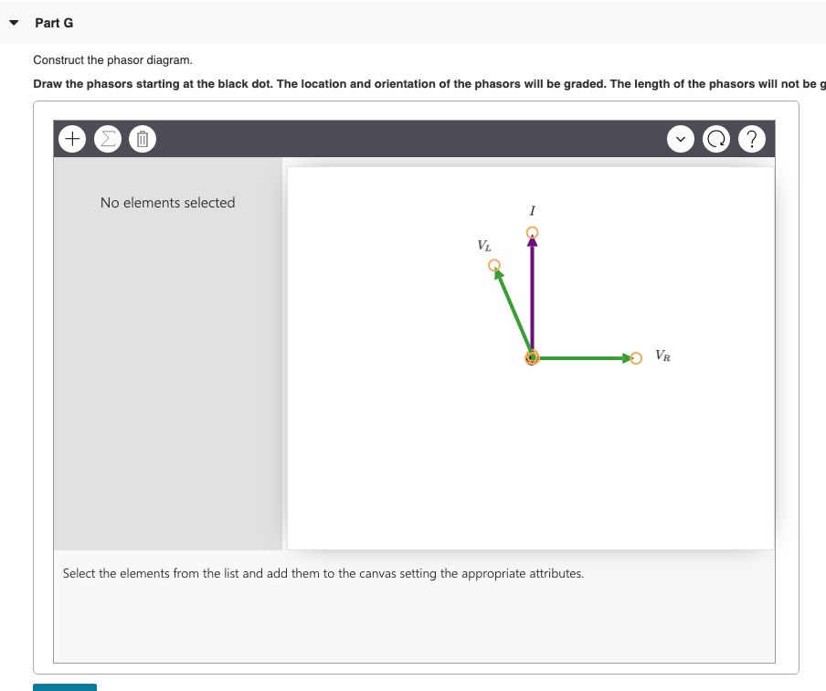
Solved: You Have A 180-Ω Resistor And A 0.370-H Inductor. | Chegg.com

Photo Credit by: bing.com /
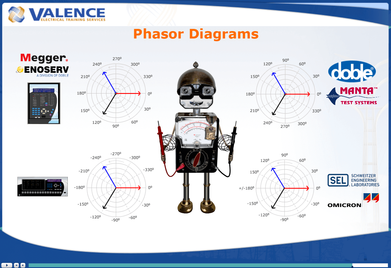
Drawing Phasor Diagrams For Relay Testers • Valence Electrical Training

Photo Credit by: bing.com / phasor draw valence phasors
What Is The Physical Significance Of Phasor Diagram Why We Use It

Photo Credit by: bing.com / phasor sinusoidal sine voltage circuits waveform phasors sinus algebra alternating ws significance functions equations brushless onda phases gelombang waveforms angular
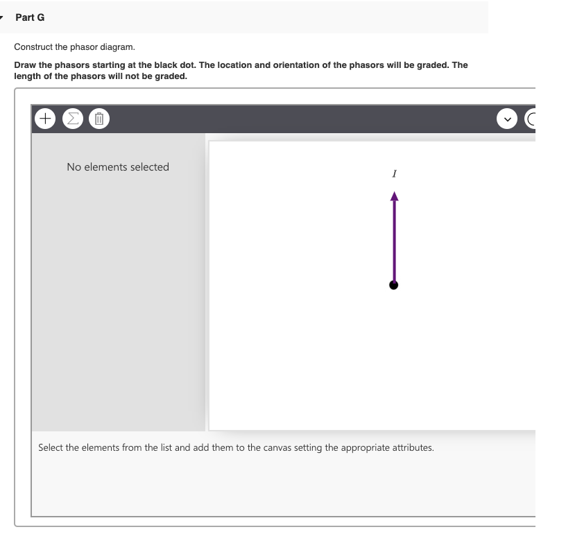
- Part 6 Construct The Phasor Diagram. Draw The | Chegg.com
Photo Credit by: bing.com / phasors phasor
Phasor Representation Of AC Current And Voltage - BYJU’S

Photo Credit by: bing.com / phasor representation voltage sinusoidal physics byju


